


Timers, counters microcontroller AVR (real time clock)
When I was first learning microcontrollers, I wanted to make hour timer , to control AC load . Frankly , I wanted to try to include a TV with only 7 to 8 hours, and the rest of the time he had to be turned off. The device I did , but it did not apply , and ...
In all AVR microcontrollers have several built-in timers . They can still be divided into general purpose timers and watchdog timer , which is intended to reboot the MK when suspended.
General purpose timers are able to :
- clocked from an external quartz clock on 32768 hertz
- consider different time intervals
- consider external shocks counter mode
- Generate PWM signal at certain conclusions MK
- generate interrupts on some event , such as an overflow
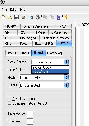
Let us consider the functional Timer/Counter1 in the microcontroller atmega8. Run CodeVision AVR, create a new project and agree to the offer to run Code WizardAVR  go to the tab Timers, further click on timer2.
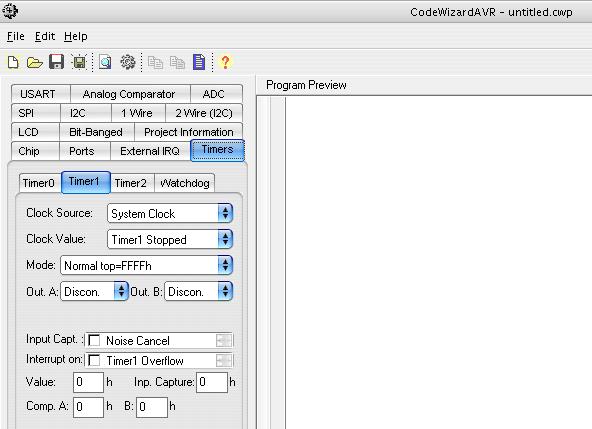
Here :
- Clock Source - clock source , here in the dropdown list , you can select
 in
in
- System Clock - timer taktiruetsya frequency at which the microcontroller running
- TOSC1 pin - the timer will operate from an external quartz legged TOSC1, TOSC2
- Clock Value - selected prescaler clock , for example if we choose prescaler 8, then every 8 clock cycles will be considered as one

Mode - specifies the mode of operation of the timer counter. U depends on the type , can be :
- Normal top - counter counts from 0 to 255 , after the overflow is reset to 0 and the count is repeated
- Fast PWM - counter counts from 0 to 255 , after the overflow is reset to 0 and the count repeated. When the values in the counting register reaches compare registers (set in line Compare), timer exposes a certain logic level (set in the drop-down list Output) on the leg OCxx
- CTC - reset the coincidence , when the values in the counting register reaches the value in the register comparison counting register is reset to zero and the count starts again.
- Phase Correct PWM - first timer counts from 0 to 255, then from 255 to 0 . Withdraw OCxx at the first match is reset in the second set .
- Overflow interrupt - interrupt is generated on overflow
- Compare Match interrupt - interrupt is generated at the coincidence
- Timer Value - initial value of the counter register
- Compare - the value of compare register
Let us for example timer2 implement real-time clock with on lcd display for this exhibit timer as shown in the screenshot

here exhibited external clock source timer as an external source , we will use the time to 32768 Hz quartz further establish prescaler 128 , ie, the timer will run at a frequency of 32768/128 = 256 and counting register is in us 8-bit (maximum number 255) , it appears that it will overflow once per second , then we are putting a checkmark beside overflow interrupt and click on file-> Generate, save and exit.
Code Wizard generated here such code
 # include <mega8.h>

// Timer2 overflow interrupt service routine
interrupt [TIM2_OVF] void timer2_ovf_isr (void)
{
}

void main (void)
{
// Input / Output Ports initialization
// Port B initialization
PORTB = 0x00;
DDRB = 0x00;

// Port C initialization
PORTC = 0x00;
DDRC = 0x00;

// Port D initialization
PORTD = 0x00;
DDRD = 0x00;

// Timer / Counter 0 initialization
// Clock source: System Clock
// Clock value: Timer 0 Stopped
TCCR0 = 0x00;
TCNT0 = 0x00;

// Timer / Counter 1 initialization
// Clock source: System Clock
// Clock value: 125,000 kHz
// Mode: Fast PWM top = 00FFh
// OC1A output: Discon.
// OC1B output: Discon.
// Noise Canceler: Off
// Input Capture on Falling Edge
// Timer1 Overflow Interrupt: Off
// Input Capture Interrupt: Off
// Compare A Match Interrupt: Off
// Compare B Match Interrupt: Off
TCCR1A = 0x01;
TCCR1B = 0x0A;
TCNT1H = 0x00;
TCNT1L = 0x00;
ICR1H = 0x00;
ICR1L = 0x00;
OCR1AH = 0x00;
OCR1AL = 0x00;
OCR1BH = 0x00;
OCR1BL = 0x00;

// Timer / Counter 2 initialization
// Clock source: TOSC1 pin
// Clock value: PCK2/128
// Mode: Normal top = FFh
// OC2 output: Disconnected
ASSR = 0x08;
TCCR2 = 0x05;
TCNT2 = 0x00;
OCR2 = 0x00;

// External Interrupt (s) initialization
// INT0: Off
// INT1: Off
MCUCR = 0x00;

// Timer (s) / Counter (s) Interrupt (s) initialization
TIMSK = 0x40;

// Analog Comparator initialization
// Analog Comparator: Off
// Analog Comparator Input Capture by Timer / Counter 1 : Off
ACSR = 0x80;
SFIOR = 0x00;

// Global enable interrupts
# asm ("sei")

while ( 1 )
      {
      };
}
Later in the timer interrupt appends count initialization time and throwing unused devices
 # include <mega8.h>
 # include <stdio.h>
// Alphanumeric LCD Module functions
# asm
   . equ __ lcd_port = 0x12; PORTD
# endasm
# include <lcd.h>
     unsigned char second = 0 ; // variable to hold seconds
     unsigned char minute = 0 ; // variable to store the minutes
     unsigned char hour = 0 ; // variable to store hours
     char lcd_buffer [ 32] ; // variable buffer to display
// Timer2 overflow interrupt service routine
interrupt [TIM2_OVF] void timer2_ovf_isr (void)
{
 if (+ + second == 59) // increase the number of seconds to check the equality of 1 and 59
 {second = 0 ;
     if (+ + minute == 59 )
     {minute = 0 ;
       if (+ + hour == 59 )
       {
        hour = 0 ;
       }
     }
 }
 lcd_clear (); // clear display before displaying
 lcd_gotoxy (0,0); // Move the cursor to the point x = 0 y = 0
 sprintf (lcd_buffer, "% i:% i:% i", hour, minute, second); // String to form the output
 lcd_puts (lcd_buffer); // Print string to display
}

void main (void)
{
// Timer / Counter 2 initialization
// Clock source: TOSC1 pin
// Clock value: PCK2/128
// Mode: Normal top = FFh
// OC2 output: Disconnected
ASSR = 0x08;
TCCR2 = 0x05;
TCNT2 = 0x00;
OCR2 = 0x00;

// Timer (s) / Counter (s) Interrupt (s) initialization
TIMSK = 0x40;

// LCD module initialization
lcd_init ( 16 );

// Global enable interrupts
# asm ("sei")

while ( 1 )
      {
      };
}
The program is ready now to chart in Proteus

You can now run the simulation. Program and the circuit in Proteus are archived time.zip . In the next article I will discuss how to use the timer can generate a PWM signal
Комментарии - (0)